Optimization of the Control System for Gas-Heated Galvanizing Furnaces Using Automation Instruments
 2021-01-21
Author: Qian Donghai
Author's Affiliation: Wuxi Xinrun Industrial Furnace Co., Ltd.
Abstract: In the production of wire hot-dip galvanizing using gas-fired furnaces, issues such as significant fluctuations in zinc temperature and excessive zinc oxide slag have been observed. To address these problems, an automatic temperature control system combining automation instruments and PLCs has been developed. Based on the operational performance of gas-fired hot-dip galvanizing furnaces at Jiangsu Fuerter Metal Products Co., Ltd. and Nantong Younuo Machinery Co., Ltd., this study analyzes and summarizes the optimization results achieved through the design and control of automation instruments for improving the heating control of hot-dip galvanizing furnaces.
Keywords: Instrumentation Automation, Galvanizing Furnace Temperature Control
Introduction: In the wire hot-dip galvanizing industry, galvanizing furnaces can be classified into several types based on their heating methods: 1. Internally heated ceramic galvanizing pot furnaces; 2. Top-heated ceramic pot furnaces; 3. Bottom-heated iron pot furnaces. This article focuses on the analysis and optimization of heating and temperature control for the second type—top-heated ceramic pot galvanizing furnaces.
Main Content
1. The Hot-Dip Galvanizing Process
Hot-dip galvanizing, as the name suggests, involves melting zinc into a liquid state under heated conditions and then immersing steel wire into it. This process allows zinc to interpenetrate with the steel wire, forming a tight bond with minimal impurities or defects in between. The two materials essentially fuse together at the zinc layer. The hot-dip galvanizing process produces steel wire with a high zinc coating thickness, resulting in excellent corrosion resistance, which has led to its widespread application in real life. The temperature control of the galvanizing furnace significantly impacts the galvanizing effect and the amount of zinc coating. Therefore, precise temperature control is crucial for galvanizing furnace equipment.
2. Control Principles of the Hot-Dip Galvanizing Furnace
The hot-dip galvanizing furnace equipment is shown in Figures 1 and 2. The equipment consists of two zones: the heating zone and the hot-dip galvanizing zone. The heating zone includes a heating cover and burners #1 and #2. Burners #1 and #2 are natural gas burners, and their power output is controlled by burner electric valves. The signal for the electric valve is a DC 4-20mA signal. The temperature control principle is illustrated in Figure 3. A thermocouple collects real-time zinc temperature signals and feeds them back to the PLC. The PLC calculates the required output using PID control based on the set zinc temperature and outputs a 4-20mA signal to drive the burner electric valve. This adjusts the burner's power to increase or decrease the furnace chamber temperature in the heating zone, ensuring that the actual zinc temperature remains stable at the set value.
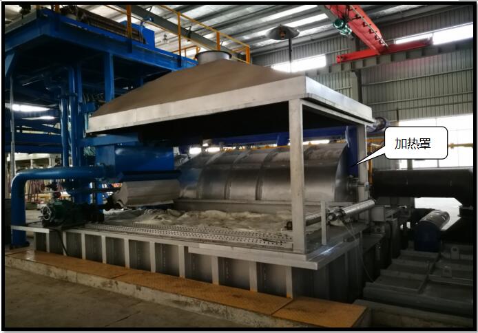
(Figure 1) Image of the Gas-Heated Galvanizing Furnace Equipment
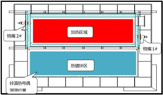
(Figure 2) Top View of the Gas-Heated Galvanizing Furnace
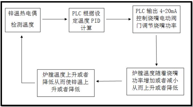
(Figure 3) Schematic Diagram of Temperature Control Working Principle
3. Problems Identified After Equipment Operation
3.1 The temperature difference between the front and back of the heating cover furnace chamber, as detected by the thermocouple, was significant, with a normal variation of 50°C to 100°C.
3.2 The zinc temperature exhibited significant lag, resulting in large PID control deviations and zinc temperature fluctuations of ±10°C.
3.3 Excessively high furnace temperatures caused localized overheating of the zinc bath, leading to the generation of large amounts of zinc oxide.
4. Equipment Improvement Using Automation Instruments
4.1 Due to the significant lag in zinc temperature control, it was difficult to achieve good control using the PLC's PID. Therefore, a zinc temperature instrument (Xiamen Yudian AI-719A2/N/N/N/N/S4/N) was added.
4.2 To address the temperature difference in the furnace chamber and make the furnace temperature rise and fall more linearly, additional thermocouples and temperature control instruments for the first and second stages were installed. These instruments are used to monitor and control the temperatures of the first and second stage furnace chambers.
(Xiamen Yudian AI719-A2/N/X3/L1/L1/S4/N)
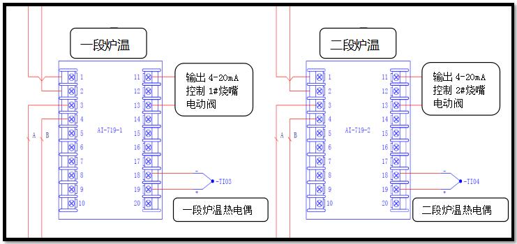
(Figure 4) Wiring Diagram of the First and Second Stage Furnace Temperature Instruments
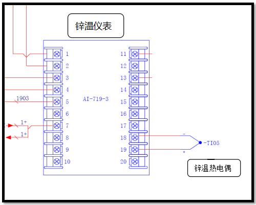
(Figure 5) Wiring Diagram of the Zinc Temperature Instrument
5. Operating Conditions After Equipment Improvement
5.1 Working Principle After Equipment Improvement
The working principle after equipment improvement is shown in Figure 6. The zinc temperature instrument performs PID calculations based on the actual zinc temperature and the set zinc temperature, with an output range of 0%–100%. The PLC reads the instrument's output (0%–100%) via its standard Modbus communication function. Through the program, the PLC converts the 0%–100% output into a temperature range of 650°C–850°C (this temperature range is empirical data summarized after on-site debugging). This calculated temperature serves as the setpoint for the first and second stage furnace temperature control instruments. Here, the standard Modbus communication function of the instrument is used again, and the set temperature is automatically written into the instrument via the communication write function. This ensures that the set temperatures of the first and second stage furnace temperature control instruments change linearly with variations in the zinc temperature, without any abrupt jumps. As the furnace temperature rises or falls, the zinc temperature also changes accordingly. The zinc thermocouple detects the real-time zinc temperature and performs PID calculations to adjust the furnace temperature setpoint, thereby achieving closed-loop control.
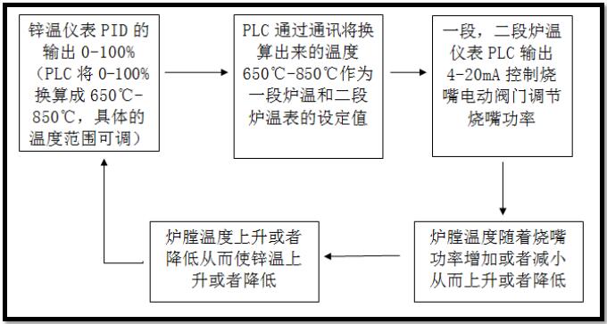
(Figure 6) Schematic Diagram of the Improved Temperature Control Working Principle
5.2 Summary After Equipment Improvement
The following optimizations to the equipment’s production and operation status were achieved after the improvement:
5.2.1 Based on the historical data exported from the equipment monitoring touch screen (Figure 7), it can be concluded that the front and rear furnace temperatures have stabilized, with a temperature difference of ±10°C or less.
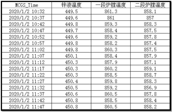
(Figure 7) On-Site Historical Data Report
5.2.2 The furnace temperature increases or decreases without any sudden jumps, showing a linear rise or fall.
5.2.3 The zinc temperature can be stabilized within ±2°C, and this temperature stability greatly contributes to maintaining a consistent zinc coating on the steel wire.
5.2.4 The automatic control system, consisting of Yudian temperature control instruments with excellent communication capabilities and mature PID algorithms combined with PLCs, demonstrates highly effective practical performance for temperature control systems with large inertia and significant delays.

TOP


